Can someone please help me learn how to setup I2C blocks for communications between Adafruit NRF52840 (or others) and other I2C units. At present I try to get a Adafruit PCF8575 Expander able to turn ON / OFF an LED, but am strugling to figure out how to do so. The address for the expander is HEX 0x20 (value 32 I believe) and the “data” addresses is two byte long.
So please teach me how to make the I2C blocks work the way I need them to, and I appreciate any help to get this to work.
Next you will see what is available so you are not re-inventing the wheel. See if someone already has done an interface. Even in a different language. If there is already an extension for MakeCode you will need to test it and possibly fix it. If it isn’t in the extension list already then there may be a reason for that. For the PCF8575 there is some C++ code. If you can translate that to Typescript then good. If not you could ask ChatGPT or Gemini or whatever to try to create one. You still need to test and fix it because AI doesn’t always get it right.
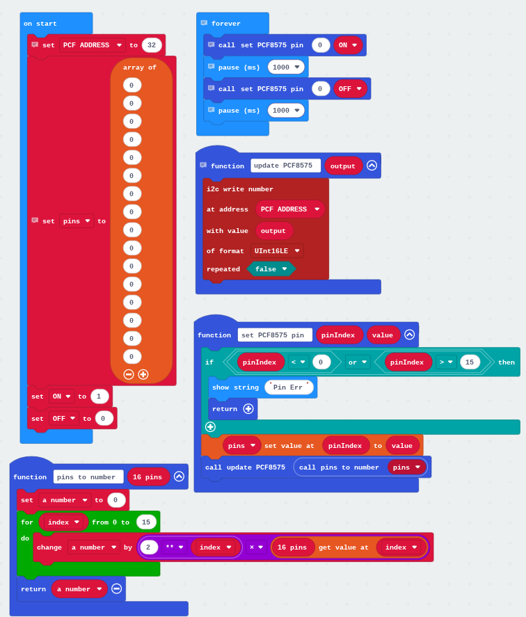
The other way to go is to use the I2C blocks from the pin library directly. Looking at the datasheet I think I would just use the Pin library. So I would start with something like this:
Hi Don, and thank you for your help. I have not yet tested what you have shown, but I will soon.
You may not have an PCF8575, but I want to learn how to make my own I2C setup using the “built-in” I2C blocks under “pins”. So if you could tell me how such a workflow would have to be done, that would be appreciatet. For now I need to figure out heads and tails of the image you have shown.
A good place to start is by reading about I2C. Perhaps here https://en.wikipedia.org/wiki/I²C. I2C is just a way to send data to another chip. What you send isn’t defined by I2C it is an agreement you make with another chip. If you make your own protocol then you get to decide what to send and receive.
For a chip like the PCF8575, here are some steps.
Read the datasheet to see what needs to be sent for a given chip.
Look for examples already written to show you what to send. For any chip there will be at least a C++ example. C++ can be ugly, just look for the function calls and their names. That usually leads to code you can understand.
Translate the examples into the I2C blocks as best as you can. Pay attention to the type of data being sent. The I2C blocks have a drop down to select the type of data.
Test it. Design an easy experiment to see if you can get something simple working first. Build on that success.
Sorry Don, but I cannot see what part does what in your example.
What reads the pins and what controls the pins (writes), and what does it potentially do with what it reads (switch input on pin) from the pins?
I would like to know how it is acutally setup in reference to the datasheet, so I can define what pins I control as outputs and what pins I read from as inputs when needed or interupted.
So please dumb it way down for me, since I am using Block editing because I don’t want to learn all about javascript nor circuitpython. Block editing is far far more logical IF somebody has created an extension for the pcb’s used in the project. That is the same with Python and to my knowledge also in most java projects.