Thanks for your answer. In this case the photo that I provided is incorrect. If I connect the signal cable in the pin 0 the problem is still happening. In this scenario (where I am connecting the servo to the PIN 2), the servo does not work (expected).
I also tried changing the code to different pins, but nothing works. In all the cases the servo spins without control
I did get my servo to spin out of control. I didn’t even know it would do that.
I found a couple of things. I was able to connect it to my oscilloscope and look at the PWM output.
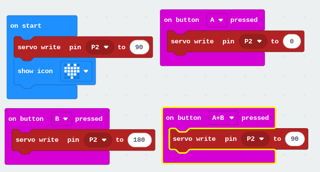
When you poll for buttons in a forever loop it does not always catch the button press. It is much more reliable to use the event handlers.
When you set the servo pulse length (using the servo write pin block) too often it causes some distortion on the pin. That seems to confuse the servo and you have to turn off the power and start over to get it working again.
The servo I have claims to run on 3.3v/5v. It lies! It needs over 5v to function properly.
The wiring you have should work it is essentially what I have. The difference being I am using 4 x AA batteries to power the servo instead of a USB connector.
And my servo spin without control (same problem than the original that I posted some days ago).
The only difference that I am seeing with your implementation and the one that I did, is that you are using 4 batteries (6V) and I am using a usb connection (power supply 5 V).
I will try to test it with a 6V power supply.
By the way, I am confused because I found several videos in youtube where the people make work the servo SG90 using a 3V power supply
Some SG90 servos claim to run on 3.3v. Maybe some do. The one I have also makes that claim. What I found in testing is that it isn’t reliable at 3.3v. Sometimes it would struggle to find the correct position. I connected up 4 AA batteries and it was much better.
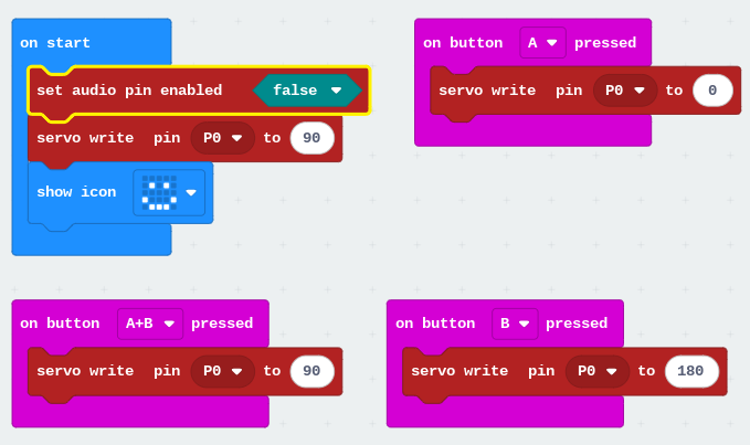
I see that the code says pin 0. P0 is also used to output sound. Use that pin only if you must. For instance if you need to control 3 servos you should use pins 0, 1, 2. Using another pin combination is not guaranteed to work with 3 servos.
Another thing I noticed is you are using a 1.5 micro:bit. I grabbed a 2.21 to test. I have a 1.5 I will test.
I am using the 1.5 micro:bit now and it does work. This time I decided to use pin 0 for the servo. As you can see to make sure the audio output can’t interfere with pin 0 I disabled it in on start.
I am not sure what the problem is that you have yet. But I wanted to make a video that shows the difference between operating a servo at 3.3v versus 5v.