If some of you are trying (very much like me :-D) to have fun with homebrew 2wd robots using the kitronik motor driver (or the equivalent), you might be able to help me a lot
I have two questions :
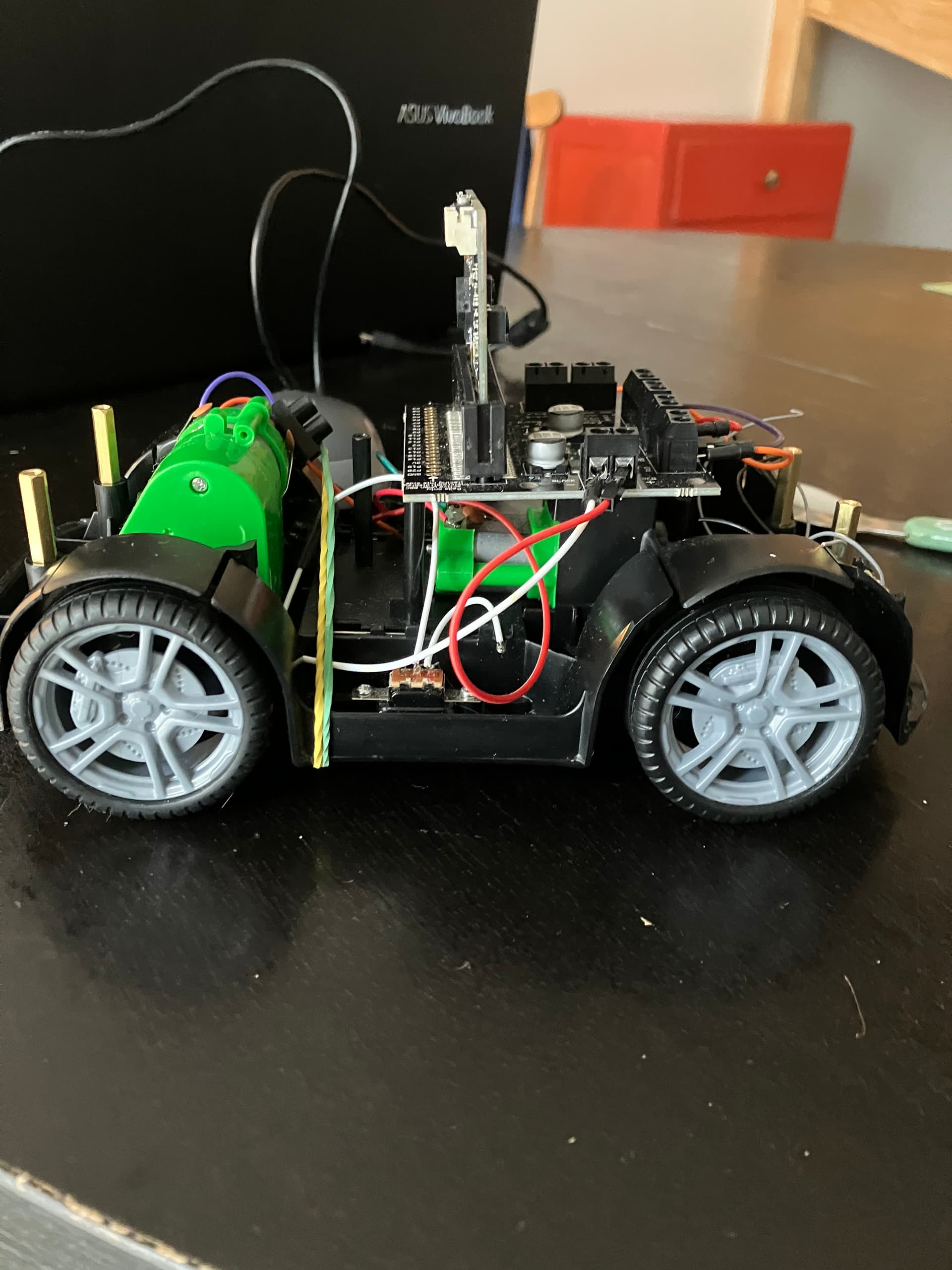
1- I started this project of a 2wheeled robot based on a old RC car a few weeks ago, and it works like a charm using 2 mircobit boards (one sender, one receiver). I can drive the car using the gyroscope and also a DFRobot gamepad (the version with the joystick : https://www.dfrobot.com/product-1711.html)
This is the kind of RC car that uses two motors : one for throttle, the other for steering.
I used this code :
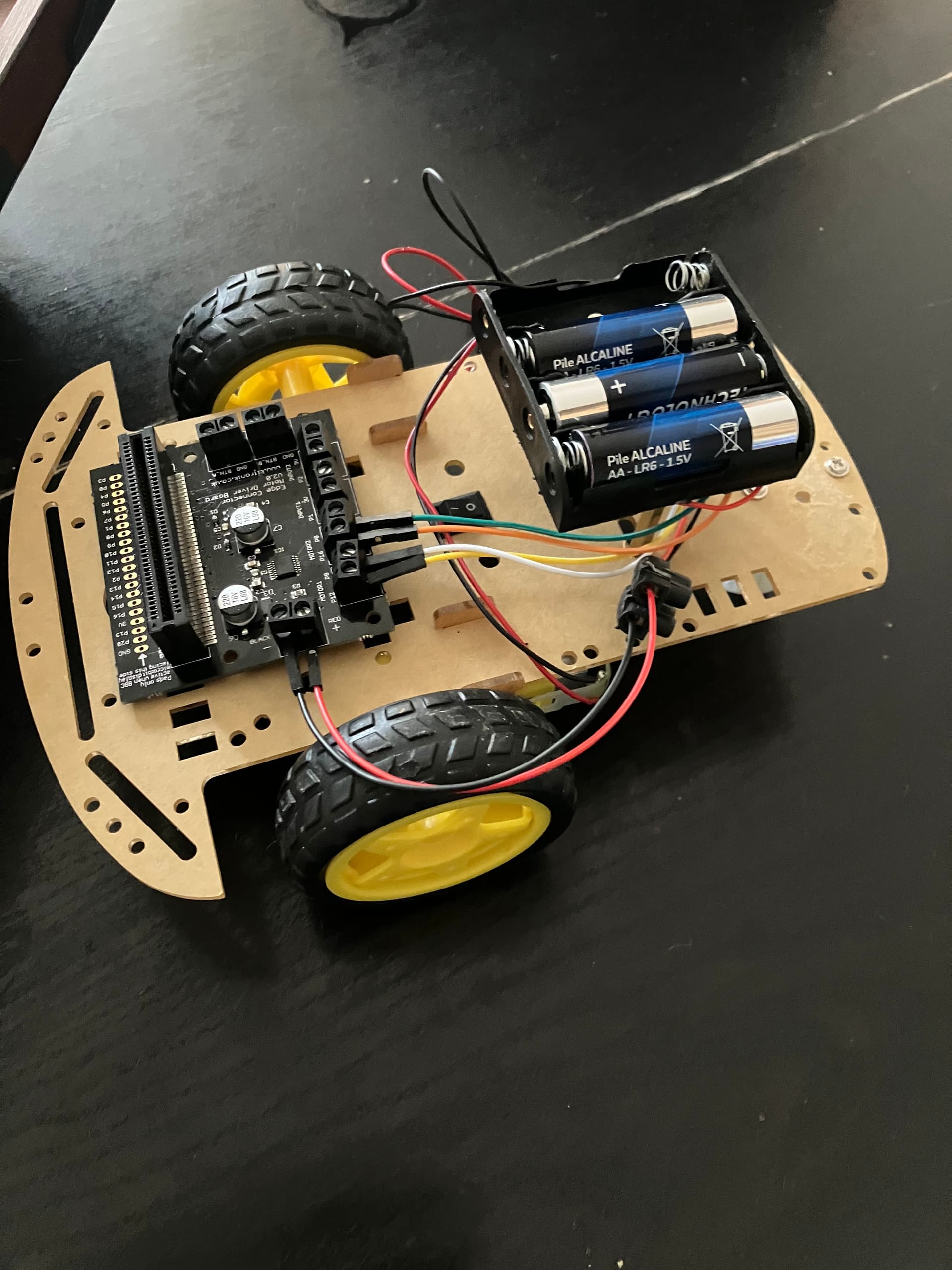
Being so happy with that, I thought it would be easy to use a simple 2WD robot chassis (two motors also but with different functions, you need to push one in a direction and the other one on the opposite to make the robot turn left or right).
And this is where the problems started. I am not sure either the problem comes from my interpretation of the code, my undersanding of how the hardware works or a strange mixture of all that but even if the robot do work, it’s extremely slow to receive radio instructions.
There is something like a 1-2 second lag between the command sent by the microbit on the gamepad and for the robot to execute the instruction). I would love to understand why this version is so slow and why the first version is so fast.
I tried to use it using random digital pins and it kind of worked on one direction but not the others… itw as weird but I just don’t understand why it shouldn’t work
If you did so, I am greatly interested on how you use this kind of hardware as a controller for a robot for example. I am interested on any link, documentation or advice on wiring and code about this kind of material. I found that the projects using the joystick module are numerous and quite well documented but I found no projects using an ARCADE joystick so far. So if you have clues about this, I would greedly appreciate. Thank you in advance
Lets deal with the hardware 1st to make sure that is working correctly ?
The DFRobot Joy pad is an analogue joy-pad, it consists of 2 potentiometers that send an analogue value ( 0 - 1024 ) to the Micro:Bit using 2 of the Micro:Bit analogue pins In this case Pin 1 + Pin 2…
The EG_Starts joystick is , i believe , a digital joystick?
This means that it is effectively 4 digital buttons/switches ( 1 for up , Left etc etc ), each of which is needs to be connected to a different pin on the Micro:Bit , So when you move the stick it will send a digital signal to the micro bit on the relevant pin depending on which direction you move it in. Just the same as if you connect 4 external buttons ,
I suggest starting a new project & connecting the Joystick to 4 of the Micro:Bits Pins - you may need to use some sort of breakout to do this as the micro:bit only give easy access to pins 0,1 ,2…
The connector on your Joystick has 5 pins ( LEFT/RIGHTUP/DOWN/ & GND)- i cannot seem to find a detailed diagram but i think this is the order on the connector?
Here is a short test MakeCode Program. Move stick in a direction & it should report the direction you moved it in .
Microsoft MakeCode
The code assumes you have connected the joystick to the following Pins on the Micro:Bit,
LEFT -----> PIN 0
RIGHT -----> PIN 1
UP -----> PIN 2
DOWN -----> PIN3
GND -----> GND
If the connector on your Joystick is in a different order you will have to change the code …
Once we have confirmed that the hardware is working correctly then we can move on to the coding for this project.
Let us know the results of this test or if you have any further questions
Good evening !
Thank you for your answer and your guidance.
Yes, I came to the conclusion that the generic arcade joystick I have (it’s not exactly the same as the one I posted earlier but with the same pinout), is indeed digital (no documentation was available with this component, it was just delivered with a USB encoder).
Anyway, I did what the test you posted using a breakout board for the microbit (and a few jumper wires), and it was concluant. The text is diplaying correctly when joystick is activated.
I kind of understood why it was not working correctly on my previous try. In fact, I just wired the joystick according to axis direction on the same pin (let’s say : up and down on digital pin 1 and so on), trying to get a value positive or negative but this can’t work as we are on digital pin…
So, in short, it works and I understand better why for the joystick arcade part. For the robot part, I still found no solution with this 2WD robot and I’m still interested in your ideas.
Meanwhile, really, thank you again for your time
Best regards,
Ok so about my robots models, there are 2 kinds of settings for the motors.
The first one is a classic RC toy car that uses 2 stepper motors (one for throttle, one for direction) see below. I have no troubles with this settings as it behaves according to the program I wrote according to your instructions about the joystick control (see program below)
I managed to make the program work with a smaller robot (DFROBOT Maqueen Lite model) but not with this one (program below)
So I’m having troubles with this one (not the Maqueen, the one in the picture). I started to wonder if that was not a hardware issue (bad or weak soldering), or just the fact that these motors draw too much current when turned on opposite direction when the “steering” command is activated : the problem is that motors start and stop randomly when turning… one of the motor seems to work much better than the other (goes forward, backward when told to) . That is where my suspicion of a bad wiring or soldering connexion comes from.
My joystick is currently installed in a nice and polished way in a wooden box(see below), and thanks to your suggestions, its can be used to drive all these robots and projects with my other microbit cards (small led matrix games etc…).
I use a smartphone powerbank to power the joystick microbit but although it’s 5V it seems safe using the USB interface.
If you have ideas or if you tried using these kinds of 2 wheels motors robots I would be interested in your feedback of course but you helped me a lot already. I did not think of pulling the pins to Up, that was the thing to do !
I stay at your disposal of course if I can help with feedback too.